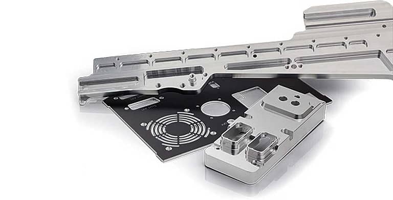
There is no question that electronics are getting smaller and smaller. As a result, electro-mechanical parts like Printed Circuit Boards (PCB), must be produced in smaller sizes. Therefore, the demand for step stencils (for stencil printing) is increasing, as well as the requirement for precision and accuracy in order to produce them with intricate detail. This article is about Step Stencil Milling and the advantages of this process over both Laser Cutting and Chemical Etching.
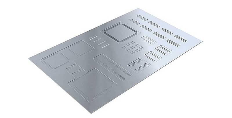
If you are not familiar with step stencils, they are metal sheets that help to control the volume of solder paste applied to specific components or features of a printed circuit board during the solder paste printing process. Because PCB’s are getting smaller and smaller, the components that populate the board have to be positioned closer and closer together. So, you can probably see the challenge here – smaller components and tighter spaces demand accuracy.
Milling vs. Laser for Step Stencil Production
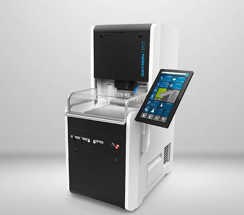
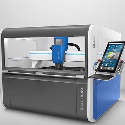
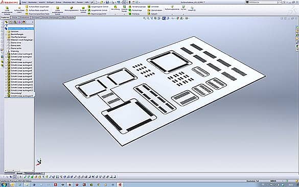
Here’s where milling comes in … and more specifically the demand for very precise high-speed milling machines. Step stencil material such as stainless steel sheets can be milled with slots and other features to reduce the thickness in desired locations. The depth of these slots (known as “steps”) need to be very precise as does their location. This is where high-speed milling has a significant advantage over laser cutting – because laser has less accuracy as well as restrictions in depth in terms of accuracy. With laser cutting, as you go deeper in the material, the laser (an intense beam of monochromatic light) tends to bend or walk. Whereas with a high-speed milling machine very precise and even depths can be maintained. As an example, the DATRON M10 Pro <3 micron runout when using HSK-E25 tool holders. If you have a need for a very large work area to produce a large step stencil or many step stencils from one sheet of material, the DATRON MLCube LS (with linear scales) delivers the same kind of accuracy and provides a 60″ x 40″ work envelope.
Milling vs. Chemical Etching for Step Stencil Production
The other process used to produce step stencils Chemical Etching. In this process, stencil material such as stainless steel is made thinner in selected areas with chemical etching. All areas that will not be made thinner (or etched) are covered with a protective film. Chemical etching is a less accurate process but is very fast. The problem is the cost and quite frankly the mess. By nature (and law), chemicals have to be managed carefully and disposed of properly, which can be very costly for the manufacturer.
High-Speed Milling Advantages for Step Stencil Production
So, getting back to the high-speed milling process, the focus should be on achieving the best production quality while saving time and obtaining a damage and residue-free stencil underside. Our customers have found that the combination of integrated probing and vacuum table workholding yield a perfectly reproducible quality, despite any material tolerances … and result in a residue-free stencil underside.
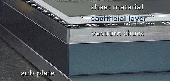
The integrated vacuum table is ideal for holding flat substrates like stainless steel sheets during the milling process. Plus, job setup is incredibly fast. The integrated probing adds to the speed of setup because the probe is used for automated part location. Additionally, the probe is used for surface scanning which records any variance in material thickness so that variance can be automatically compensated for in the milling program. This means that the depth of milled features (or steps) on the stencil will be deadly accurate!
- Time Savings: faster than laser
- No thermal degradation of the material structure
- Absolute and constant accuracy in rapid removal of material
- No costly chemicals, or chemical disposal