Looking to Get A Perfect Surface Finish?
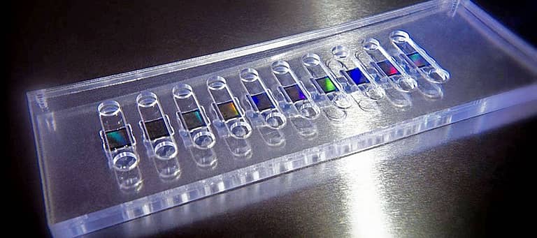
There are many factors when trying to achieve the perfect surface finish on a machined 3D part. This blog will focus on the toolpath filtering options for CNC machines and CAM software.
Toolpath Filter in CAM Software
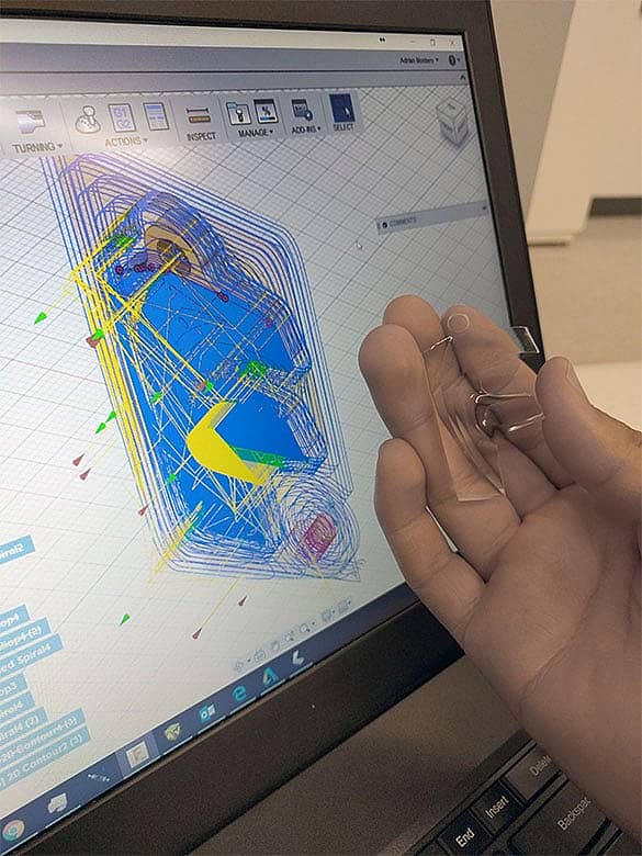
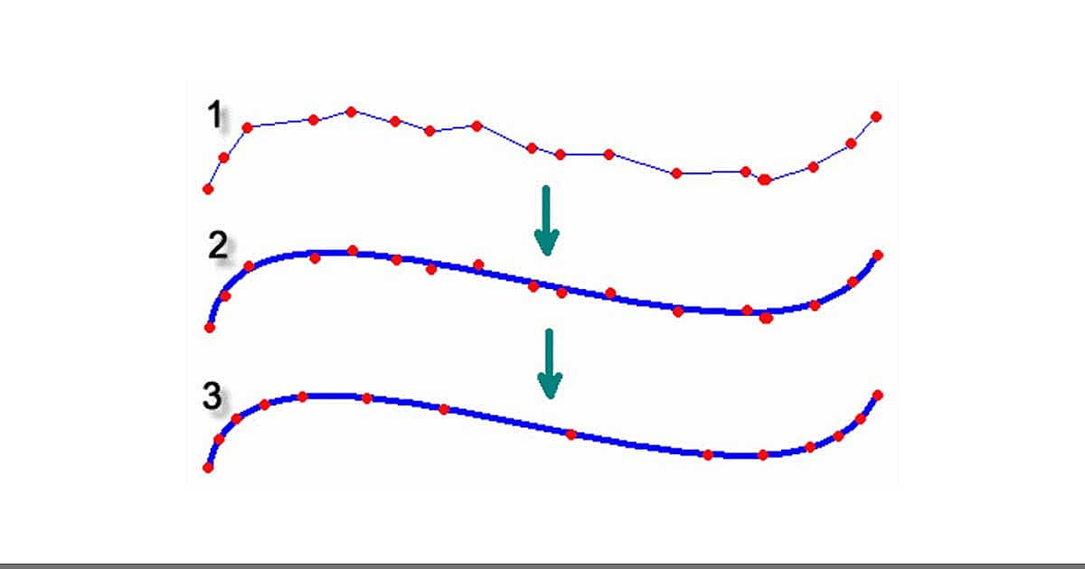
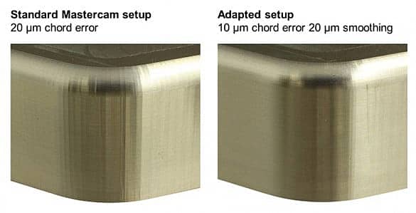
Filtering and smoothing options exist in CAM software and work by shifting and removing points. In many CAM systems, you’re able to set a tolerance for how accurately you’d like to follow the surface with the tool. If you have a large tolerance set in your CAM, you’ll lose detail or tolerance on your part. On the other hand, if you set the tolerance too low, you’ll have more code, so processing time increases along with the risk of vector points being visible on your part’s surface.
Toolpath Filter in CNC Milling Machine Control Software
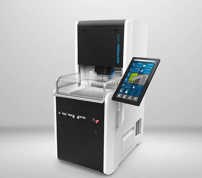
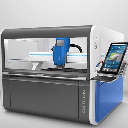
But what about using a smoothing feature on the milling machine itself? That’s available with DATRON’s next and HSC Pro software. They have a proprietary smoothing toolpath filter that works on a totally different basis. Instead of removing points and losing tolerance on your part as with the smoothing function in CAM, the toolpath filter adds points within the tolerance set in the CAM. The machine also calculates to five decimal places (metric) to provide a more accurate surface. By adding points and increasing the read ahead of the machine, you don’t have to worry about losing detail while creating a smooth finish. The DATRON smoothing toolpath filter also monitors the jerk. Monitoring the jerk of the motors ensures a smooth machine motion while eliminating excess stress on the machine at high feed rates.
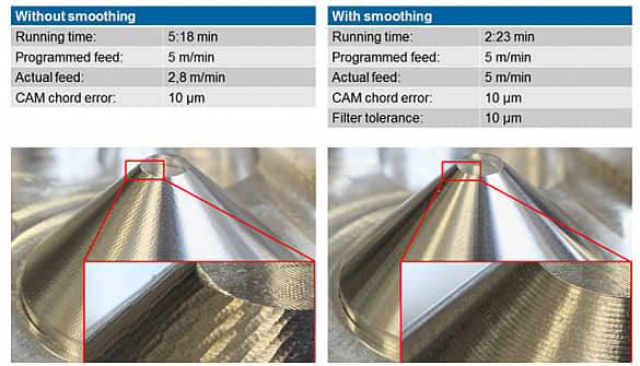
So in conclusion, by running a smoothing toolpath filter in the machine, you get faster calculation time from your CAM, along with a more accurate part requiring less optimization in the CAM software. For more machining and programming tips, explore our blog.